Size:
5.24
MB
〈Catalog〉Industrial Water Quality Measuring Instruments

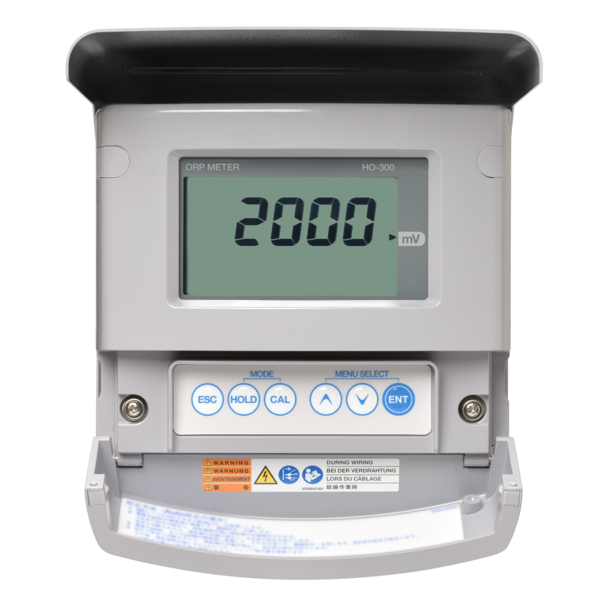
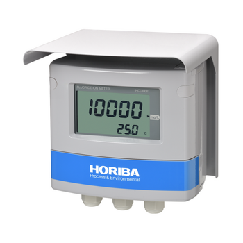
Field-installation type ORP meter
Suitable for managing neutralization reaction processes such as aeration tanks and denitrification tanks. We offer a wide range of cleaning devices to accommodate a variety of samples.
![]()
![]()
![]()
![]()
![]()
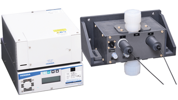
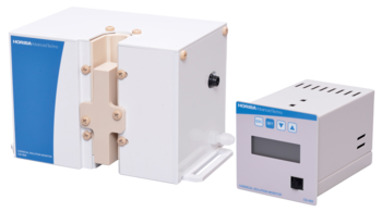
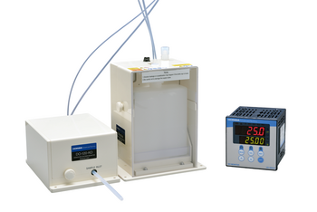
Comprehensive range of cleaning devices.
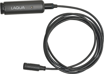
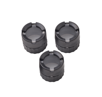
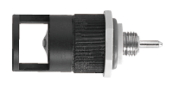
A diverse lineup of cleaning devices are offered. Particularly, ultrasonic cleaners are advantageous as they do not require water or air, making them convenient for retrofitting existing HO-300 installations on site. The drop-in type of cleaning device, which fits into a holder, offers ease of maintenance.
| Product name | ORP meter | |||
|---|---|---|---|---|
| Model | HO-300 | |||
| Combined sensor | ORP electrode | |||
| Measurable range | ORP | −2000 mV to 2000 mV (display range: −2200 mV to 2200 mV) | ||
| Temperature | 0℃ to 100℃
| |||
| Display resolution | ORP | 1 mV | ||
| Temperature | 0.1℃ | |||
| Performance | ORP | Repeatability | Within ±5mV (response for equivalent input) | |
| Linearity | Within ±5mV (response for equivalent input) | |||
| Temperature | Repeatability | ±0.3℃ (response for equivalent input) | ||
| Linearity | ±0.3℃ (response for equivalent input) | |||
| Transmission output | Output type | 4 mA to 20 mA DC: input/output insulation type | ||
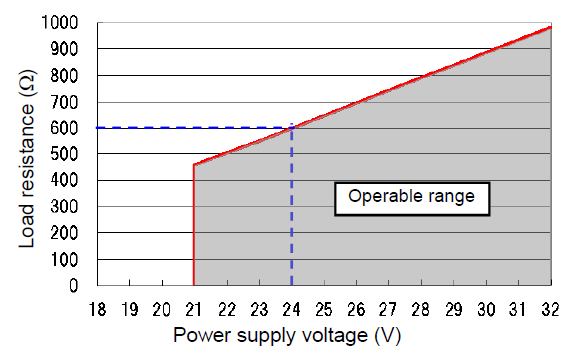
| Load resistance | Max.: 600Ω (case of 24 V DC power supply)*1 | |||
| Linearity | Within ±0.08 mA (output only) | |||
| Repeatability | Within ±0.02 mA (output only) | |||
| Output range | ORP: Selection from preset ranges or free range input within measuring range. | |||
| Occasional out for error | Hold or burnout to either 3.8 mA or 21 mA | |||
| Transmission hold | In the maintenance mode, transmission signal is held at the latest value or preset value. In the calibration mode, transmission signal can be alive or held. | |||
| Contact input | Number of input points | 1 | ||
| Contact type | No-voltage a-contact | |||
| Conditions | ON resistance: 40 Ω Open voltage: 1.2 V Short-circuit current: 21 mA DC max. | |||
| Contact function | External input for transmission holding. | |||
| Temperature measurement | Applicable temperature element | Platinum resistor: 1 kΩ (0℃) | ||
| Positive relation resistor with temperature: 500 Ω (25℃), 6.8 kΩ (25℃), 10 kΩ (25℃) | ||||
| Element selection method | Automatic temperature sensor type detection or manual selection (no temperature element is selectable) | |||
| Calibration | ORP adjust function | Adjust (offset adjustment): −200 mV to 200 mV Span sensitivity correction: 0.500 to 1.500 | ||
| Temperature calibration | 1 point calibration comparing reference thermometer | |||
| Self-check | Calibration error | Temperature calibration error Out of temperature calibration range (for ORP sensor with RTD). | ||
| Electrode diagnostic error | Reference electrode impedance error (only applicable for differential circuit mode with a liquid contact electrode) Temperature sensor short-circuit, temperature sensor disconnection, and out of the temperature measurement range | |||
| Converter error | CPU, ADC, and memory errors | |||
| Operating temperature range | −20℃ to 60℃ (without freeze) | |||
| Operating humidity range | Relative humidity: 5% to 90% (without condensation) | |||
| Storage temperature | −25℃ to 65℃ | |||
| Power supply | Rated voltage | 24 V DC (operating voltage range: 21 V to 32 V DC)*1 | ||
| Power consumption | 0.6 W or less. | |||
| Compatible standards | CE marking | |||
| Compatible standards | EMC directive: EN61326-1 RoHS Directive: EN50581 | |||
| Immunity | Industrial electromagnetic environment | |||
| Electostatic discharge | IEC61000-4-2 | |||
| Electromagnetic field of radiated radio frequency | IEC61000-4-3*2 | |||
| Electric fast transient/burst | IEC61000-4-4 | |||
| Surge | IEC61000-4-5*3 | |||
| Conducted interference induced by radio frequency | IEC61000-4-6*2 | |||
| Emission | Class A | |||
| Radiated disturbance | CICPR 11 CLASS A | |||
| FCC Rules | Part15 CLASS A | |||
| Structure | Installation | Outdoor installation type | ||
| Installation method | Mounted on 50 A pole or wall | |||
| Protection code | IP65 | IEC60529, JIS C0920 | ||
| Case material | Aluminum alloy (coated with epoxy-denatured melamine resin) | |||
| Material of fittings | SUS304 | |||
| Material of hood | SUS304 (coated with epoxy modified melanine resin) | |||
| Material of window | Polycarbonate | |||
| Display element | Reflective monochrome LCD | |||
| External dimensions | 180 (W) mm × 155 (H) mm × 115 (D) mm (excluding mounting brackets) | |||
| Mass | Main body: approx. 2.8 kg, Hood and mounting brackets: approx. 1 kg | |||
Though an arrester (spark over voltage: 400 V) is implemented for transmission output, use a most suitable surge absorption element on the connection lines in accordance with the ambient environment, the situation of equipment installed, and the externally connected equipment.
Do you have any questions or requests? Use this form to contact our specialists.

ORP Sensor Cartridge for WQ-300 series
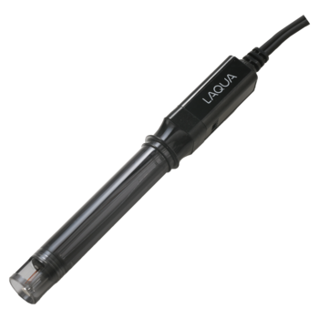
Plastic body Non-refillable ORP electrode

Fiber Optic Type Chemical Concentration Monitor
Optical Fiber Type Hot Phosphoric Acid Concentration Monitor
Non-Contact Chemical Concentration Monitor

Standard type

For measurement of low-conductivity water and non-aqueous solvents.

Field-installation type water quality measuring instruments

Field-installation Type Fluoride Ion Concentration Meter

Field-installation type ammonia nitrogen meter
Field-installation Type Fluoride Ion Concentration Meter

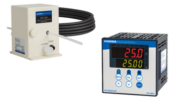
Field-installation type dissolved oxygen meter (DO meter)

Field-installation type optical dissolved oxygen meter (DO meter)

Field-installation type dissolved oxygen meter (DO meter)

Panel-mount type dissolved oxygen meter (DO meter)

HF (Hydrofluoric Acid) DO (Dissolved Oxygen) Monitor / Pure Water DO (Dissolved Oxygen) Monitor
Dissolved Oxygen Concentration Monitor Series for Semiconductor Manufacturing

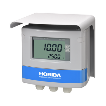
Field-installation type electric conductivity meter (conductivity meter)

Field-installation type electric conductivity meter

Field-installation type electric resistivity meter (resistivity meter)
Field-installation type electrical conductivity meter (conductivity meter)

Field-installation type electric resistivity meter (resistivity meter)
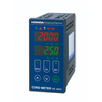
Panel-mount type conductivity meter (conductivity meter)

Carbon Sensor Conductivity Meter (Low concentration type)

Panel-mount type conductivity meter (conductivity meter)

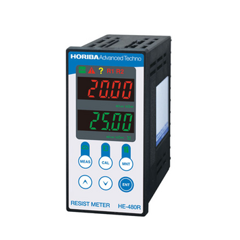
Panel-mount type resistivity meter (resistivity meter)
Resistivity Meter for Semiconductor Cleaning Processes

Citric Acid Monitor
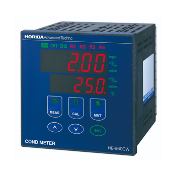
Panel-mount type 2-channel conductivity meter (conductivity meter)

KOH Monitor
Wide range TMAH Concentration Monitor
High Precision TMAH Concentration Monitor
Field-installation type water quality measuring instruments
Field-installation type dissolved oxygen meter (DO meter)
Field-installation type dissolved oxygen meter (DO meter)
Panel-mount type dissolved oxygen meter (DO meter)
HF (Hydrofluoric Acid) DO (Dissolved Oxygen) Monitor / Pure Water DO (Dissolved Oxygen) Monitor
Dissolved Oxygen Concentration Monitor Series for Semiconductor Manufacturing
Field-installation type electric conductivity meter (conductivity meter)
Field-installation type electric conductivity meter
Field-installation type electric resistivity meter (resistivity meter)
Field-installation type electrical conductivity meter (conductivity meter)
Field-installation type electric resistivity meter (resistivity meter)
Panel-mount type conductivity meter (conductivity meter)
Carbon Sensor Conductivity Meter (Low concentration type)
Panel-mount type conductivity meter (conductivity meter)
Panel-mount type resistivity meter (resistivity meter)
Resistivity Meter for Semiconductor Cleaning Processes
Citric Acid Monitor
Panel-mount type 2-channel conductivity meter (conductivity meter)
KOH Monitor
Wide range TMAH Concentration Monitor
High Precision TMAH Concentration Monitor
Carbon Sensor Conductivity Meter (High concentration type)
Panel-mount type conductivity meter
Carbon Sensor Conductivity Meter
Flat Carbon Sensor Conductivity Meter
Carbon Sensor Resistivity Meter
Panel-mount type 2-channel electric resistivity meter (resistivity meter)
2-Channel Resistivity Meter
Low Concentration Monitor- Sulfuric Acid/Hydrogen Peroxide
HF / HCl Concentration Monitor
Low Concentration Type HF/HCl/NH3 Concentration Monitor
Field-installation type ORP meter
Panel-mount type ORP meter
Field-installation type polarographic residual chlorine meter
Field-installation type residual chlorine meter
Panel-mount type galvanic residual chlorine meter
On-line TOC analyzer
")
")
")
")
")
")
")
")
")

")
")
")
")
")
")

")
")
")
")
")
")
")


")
")
")
")
")
")
")


")


,HE-960LC")


")

")


