Size:
5.24
MB
〈Catalog〉Industrial Water Quality Measuring Instruments

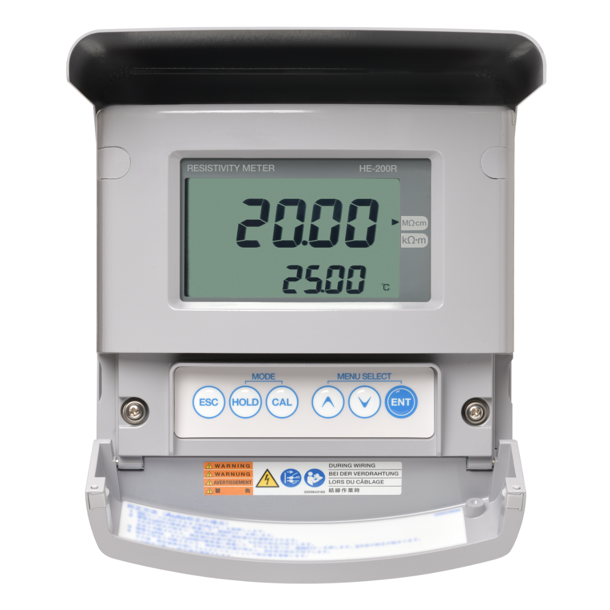
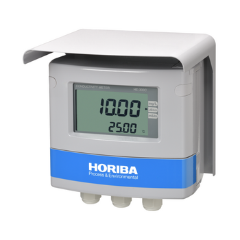
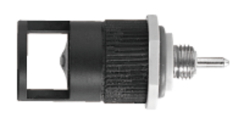
Field-installation type electric resistivity meter (resistivity meter)
Combined with the electric resistivity sensor (ERF series), it measures the electric resistivity and temperature of aqueous solutions. Suitable for measuring electric resistivity of UPW.
![]()
![]()
![]()
![]()
![]()
![]()
![]()
Enables measurements with minimal error
Measurements are affected less by ambient temperature and sample temperature, enabling accurate measurements with less error.
We provide equipment and sensor calibration services
Temperature sensor offset calibration is offered as well as converter and sensor combination calibration services. *Option
Highly responsive temperature sensor
Helps to minimize fluctuations in measurement values due to delayed temperature compensation in the event of sudden changes in water temperature.
| Product name | Resistivity meter | |||
|---|---|---|---|---|
| Model | HE-200R | |||
| Combined sensor | 2-electrode method resistivity sensor (ERF-001 Series) of cell constant 0.01/cm | |||
| Measuring range | Resistivity | MΩ•cm | 0.000 to 2.000 | 0.00 to 20.00 (*Note 1) |
| kΩ•cm | 0.00 to 20.00 | 0.0 to 200.0 (*Note 1) | ||
| Temperature | ℃ | 0℃ to 100℃ (Display range: −10℃ to 110℃) | ||
| Display resolution | Resistivity | As shown in the measuring table. | ||
| Temperature | 0.01℃ | |||
| Performance | Resistivity | Repeatability | Within ±0.1% of the full scale (response for equivalent input) | |
| Linearity | Within ±0.5% of the full scale (response for equivalent input) | |||
| Temperature | Repeatability | ±0.1℃ (response for equivalent input) | ||
| Linearity | ±0.5℃ (response for equivalent input) | |||
| Transmission output | Number of output | 2 (The negative terminals for transmission outputs are internally connected at the same electric potential) | ||
| Output type | 4 mA to 20 mA DC: input/output isolated type | |||
| Load resistance | Maximum: 900Ω | |||
| Linearity | Within ±0.08 mA (output only) | |||
| Repeatability | Within ±0.02 mA (output only) | |||
| Output range | Output 1 | Resistivity: Free setting within a measuring range. | ||
| Output 2 | Temperature: Free setting within a range between −20 and 130℃ | |||
| Occasional out for error | Hold or burnout to either 3.8 mA or 21 mA | |||
| Transmission hold | In the maintenance mode, transmission signal is held at the latest value or preset value. In the calibration mode, transmission signal can be alive or held. | |||
| Contact output | Number of output | 3 | ||
| Output type | No-voltage contact output | |||
| Contact type | Relay contact; SPDT (1c) | |||
| Contact capacity | 250 V AC, 3 A; 30 V DC, 3 A (resistance load) | |||
| Contact function | R1, R2 | Selectable from upper limit alarm, lower limit alarm, and currently holding of transmission output. (The contact is closed during alarm operation, opened normally and while the power is down.) | ||
| FAIL | Error alarm (Closed in the normal state, opened in the failure state or while the power is down.) | |||
| Alarm setting range |
| |||
| Contact input | Number of input points | 1 | ||
| Contact type | No-voltage "a" contact for open collector | |||
| Conditions | ON resistance: 100 Ω max. Open voltage: 24 V DC Short-circuit current: 12 mA DC max. | |||
| Contact function | External input for transmission holding. | |||
| Transmission capability | Method | RS-485 | ||
| Signal type | 2 wire system, isolated from the input circuit Not isolated from transmission circuit | |||
| Temperature compensation | Applicable temperature element | Platinum resistor: 1 kΩ (0℃) | ||
| Compensation method |
| |||
| Temperature compensation range | 0℃ to 100℃ (However, the compensation calculation is extended lower than 0℃ or higher than 100℃.) | |||
| Calibration | Resistivity | Based on parameter input of coefficient for the sensor cell constant. | ||
| Temperature | Comparison to the accurate thermometer Both deviation and coefficient of RTD are taken into account for calibration. | |||
| Other function | UPW standard resistivity input | Select one from the next. 182.3 kΩ•m (standard), 181.8 kΩ•m, 182.4 kΩ•m, 18.23 MΩ•cm (standard), 18.18 MΩ•cm, or 18.24 MΩ•cm | ||
| Clipping function | If the measured value exceeds the user setting value for clipping, the measured data will be held at the clipping value. | |||
| Self-check | Sensor diagnostic error | Temperature sensor short-circuit, temperature sensor disconnection, and out of the temperature measurement range | ||
| Converter error | CPU, ADC, and memory errors | |||
| Operating temperature range | −20℃ to 55℃ (without freeze) | |||
| Operating humidity range | Relative humidity: 5% to 90% (without condensation) | |||
| Storage temperature | −25℃ to 65℃ | |||
| Power supply | Rated power supply voltage | 100 V to 240 V AC ±10% 50/60 Hz | ||
| Power consumption | 15 VA (max) | |||
| Other | With power switch for maintenance use | |||
| Compatible standards | CE marking | EMC :EN61326-1 Class A, Industrial electromagnetic environment Safety :EN61010-1 RoHS :EN50581 9. Industrial monitoring and control instruments | ||
| FCC rules | Part15 Class A | |||
| Structure | Installation | Outdoor installation type | ||
| Installation method | Mount on 50 A pole or wall | |||
| Protection code | IP65 | |||
| Case material | Aluminum alloy (coated with epoxy-denatured melamine resin) | |||
| Material of fittings | SUS304 | |||
| Material of hood | SUS304 stainless steel (coated with epoxy denatured melamine resin) | |||
| Material of window | Polycarbonate | |||
| Display element | Reflective monochrome LCD | |||
| External dimensions | 180 (W) mm × 155 (H) mm × 115 (D) mm (excluding cover and mounting brackets) | |||
| Mass | Main body: Approx. 3.5 kg; cover and mounting brackets: Approx. 1 kg | |||
Do you have any questions or requests? Use this form to contact our specialists.

Fiber Optic Type Chemical Concentration Monitor
Optical Fiber Type Hot Phosphoric Acid Concentration Monitor
Non-Contact Chemical Concentration Monitor

Field-installation type water quality measuring instruments

Field-installation Type Fluoride Ion Concentration Meter

Field-installation type ammonia nitrogen meter
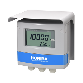
Field-installation Type Fluoride Ion Concentration Meter

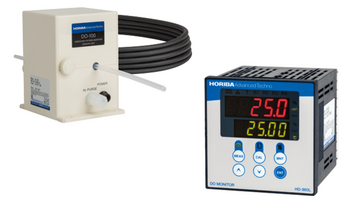
Field-installation type dissolved oxygen meter (DO meter)

Field-installation type optical dissolved oxygen meter (DO meter)

Field-installation type dissolved oxygen meter (DO meter)

Panel-mount type dissolved oxygen meter (DO meter)

HF (Hydrofluoric Acid) DO (Dissolved Oxygen) Monitor / Pure Water DO (Dissolved Oxygen) Monitor
Dissolved Oxygen Concentration Monitor Series for Semiconductor Manufacturing

Field-installation type electric conductivity meter (conductivity meter)

Field-installation type electric conductivity meter
Field-installation type electrical conductivity meter (conductivity meter)

Field-installation type electric resistivity meter (resistivity meter)
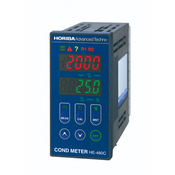
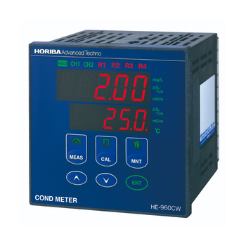
Panel-mount type conductivity meter (conductivity meter)

Carbon Sensor Conductivity Meter (Low concentration type)

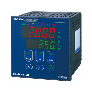
Panel-mount type conductivity meter (conductivity meter)

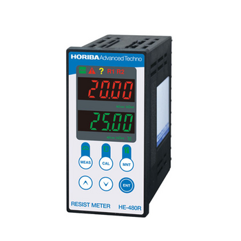
Panel-mount type resistivity meter (resistivity meter)
Resistivity Meter for Semiconductor Cleaning Processes

Citric Acid Monitor
Panel-mount type 2-channel conductivity meter (conductivity meter)

KOH Monitor
Wide range TMAH Concentration Monitor
High Precision TMAH Concentration Monitor
,HE-960LC")
Carbon Sensor Conductivity Meter (High concentration type)
Panel-mount type conductivity meter
Carbon Sensor Conductivity Meter

Flat Carbon Sensor Conductivity Meter
")
Carbon Sensor Resistivity Meter
Field-installation type water quality measuring instruments
Field-installation type dissolved oxygen meter (DO meter)
Field-installation type dissolved oxygen meter (DO meter)
Panel-mount type dissolved oxygen meter (DO meter)
HF (Hydrofluoric Acid) DO (Dissolved Oxygen) Monitor / Pure Water DO (Dissolved Oxygen) Monitor
Dissolved Oxygen Concentration Monitor Series for Semiconductor Manufacturing
Field-installation type electric conductivity meter (conductivity meter)
Field-installation type electric conductivity meter
Field-installation type electrical conductivity meter (conductivity meter)
Field-installation type electric resistivity meter (resistivity meter)
Panel-mount type conductivity meter (conductivity meter)
Carbon Sensor Conductivity Meter (Low concentration type)
Panel-mount type conductivity meter (conductivity meter)
Panel-mount type resistivity meter (resistivity meter)
Resistivity Meter for Semiconductor Cleaning Processes
Citric Acid Monitor
Panel-mount type 2-channel conductivity meter (conductivity meter)
KOH Monitor
Wide range TMAH Concentration Monitor
High Precision TMAH Concentration Monitor
Carbon Sensor Conductivity Meter (High concentration type)
Panel-mount type conductivity meter
Carbon Sensor Conductivity Meter
Flat Carbon Sensor Conductivity Meter
Carbon Sensor Resistivity Meter
Panel-mount type 2-channel electric resistivity meter (resistivity meter)
2-Channel Resistivity Meter
Low Concentration Monitor- Sulfuric Acid/Hydrogen Peroxide
HF / HCl Concentration Monitor
Low Concentration Type HF/HCl/NH3 Concentration Monitor
Field-installation type ORP meter
Field-installation type ORP meter
Panel-mount type ORP meter
Field-installation type polarographic residual chlorine meter
Field-installation type residual chlorine meter
Panel-mount type galvanic residual chlorine meter
On-line TOC analyzer
")
")
")
")
")
")
")
")
")
")

")
")
")
")
")
")

")
")
")
")
")
")
")


")
")
")
")
")
")
")


")


,HE-960LC")


")

")


