Size:
5.24
MB
〈Catalog〉Industrial Water Quality Measuring Instruments

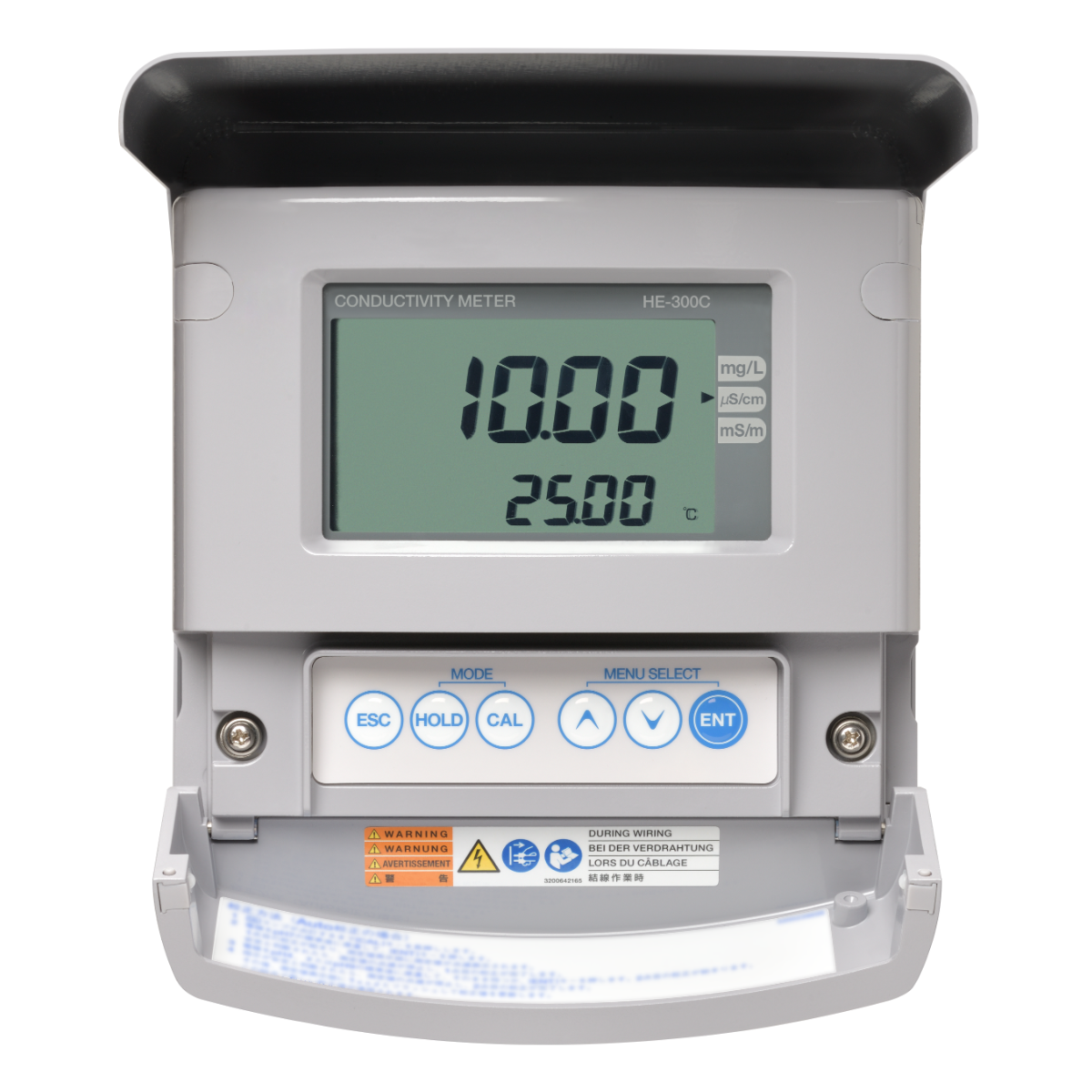
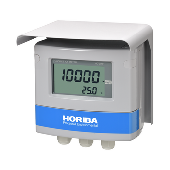
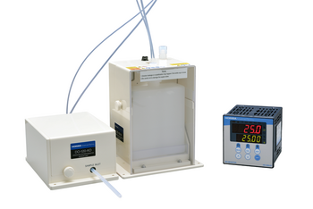
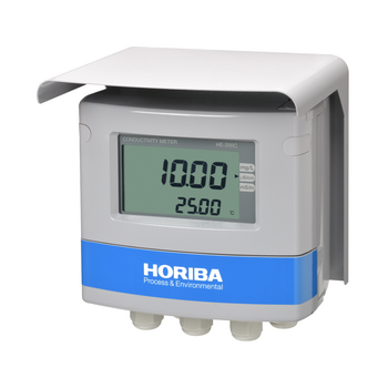
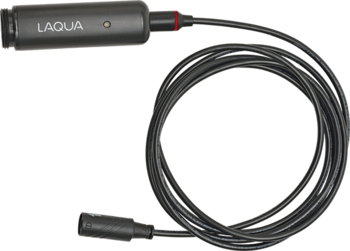
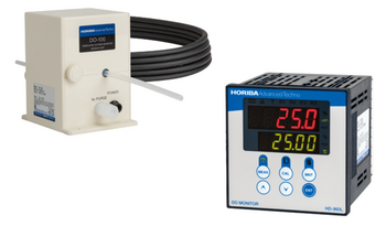
Field-installation type electrical conductivity meter (conductivity meter)
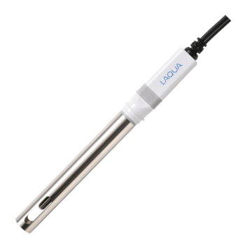
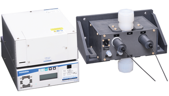
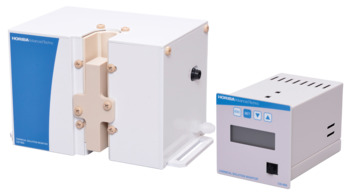
Combined with electrical conductivity sensors (ESH/FS series) to measure electrical conductivity and temperature of water samples. Suitable for measurement of pure water and boiler water. A lineup of sensors for pharmaceutical manufacturing processes that comply with the pharmacopoeias (USP, EP, JP) of various countries are also offered.
![]()
![]()
![]()
![]()
![]()
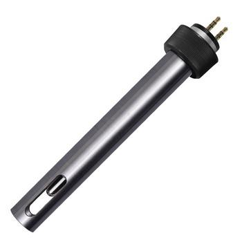
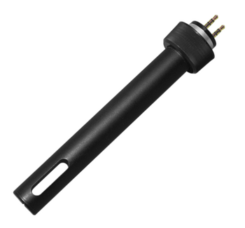
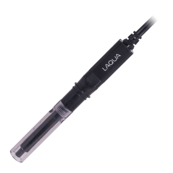
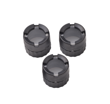
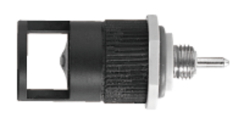
Diverse lineup of sensors available
Sensors that are tailored to match the sample characteristics and applications are proposed.
Highly robust
Required accessories and wiring for installation possess the ruggedness appropriate for industrial applications, ensuring they can withstand harsh environmental conditions.
| Product name | Conductivity meter | ||||
|---|---|---|---|---|---|
| Model | HE-300C | ||||
| Sensors in combination | 2-electrode method conductivity sensor ESH and FS Series sensor of cell constant 0.01/cm, 0.1/cm, or 1.0/cm | ||||
| Measurable range (*Note 1) | Cell constant (/cm) | 0.01 (ESH-001) | 0.1 (ESH/FS-01) | 1.0 (ESH-1) | |
| Unit | |||||
| Conductivity | μS/cm | 0.000 to 2.000 0.00 to 10.00 | 0.000 to 2.000 0.00 to 20.00 0.0 to 100.0 | 0.0 to 200.0 0 to 1000 | |
| mS/m | 0.0000 to 0.2000 0.000 to 1.000 | 0.0000 to 0.2000 0.000 to 2.000 0.00 to 10.00 | 0.00 to 20.00 0.0 to 100.0 | ||
| TDS conversion | mg/L | 0.00 to 2.00 0.0 to 10.0 | 0.00 to 2.00 0.0 to 20.0 0 to 100 | 0 to 200 0 to 1000 | |
| Temperature | ℃ | 0 to 100 (display range: −10℃ to 160℃) | |||
| Display resolution | Conductivity / TDS conversion | As shown in the measuring table. | |||
| Temperature | 0.01℃ | ||||
| Performance | Conductivity | Repeatability | Within ±0.5% of the full scale (response for equivalent input) Within ±5% of the full scale in the range of 2000 μS/cm or 200 mS/m for FS-01 sensor | ||
| Linearity | Within ±0.5% of the full scale (response for equivalent input) Within ±5% of the full scale in the range of 2000 μS/cm or 200 mS/m for FS-01 sensor | ||||
| TDS conversion | Repeatability | Within ±1.5% of full-scale value (response for equivalent input) | |||
| Linearity | Within ±1.5% of full-scale value (response for equivalent input) | ||||
| Temperature | Repeatability | ±0.1℃(response for equivalent input) | |||
| Linearity | ±0.5℃(response for equivalent input) | ||||
| Transmission output | Output type | 4 mA to 20 mA DC input/output insulation type (two-wire transmission type) | |||
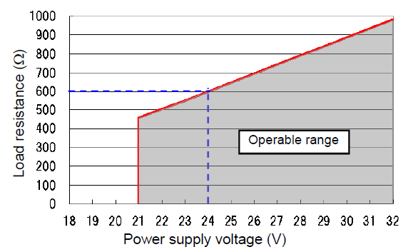
| Load resistance | Maximum: 600 Ω. Case of 24 V DC power supply (*Note 3) | ||||
| Linearity | Within ±0.08 mA (output only) | ||||
| Repeatability | Within ±0.02 mA (output only) | ||||
| Output range | Conductivity: Free setting within a measuring range. | ||||
| Occasional out for error | Hold or burnout to either 3.8 mA or 21 mA | ||||
| Transmission hold | In the maintenance mode, transmission signal is held at the latest value or preset value. In the calibration mode, transmission signal can be alive or held. | ||||
| Contact input | Number of input points | 1 | |||
| Contact type | No-voltage a-contact | ||||
| Conditions | ON resistance: 40 Ω max. Open voltage: 1.2 VDC Short-circuit current: 21 mA DC max. | ||||
| Contact function | External input for transmission holding. | ||||
| Temperature compensation | Temperature element | Platinum resistor: 1 kΩ (0℃) | |||
| Temperature compensation |
| ||||
| Temperature compensation range | 0℃ to 100℃ (However, the compensation calculation is extended lower than 0℃ or higher than 100℃.) | ||||
| Temperature calibration | 1 point calibration comparing to reference thermometer | ||||
| Calibration | Conductivity | Based on parameter input of coefficient for the sensor cell constant. | |||
| TDS conversion | Conversion by user-defined coefficient value (TDS calculation is 0.30 to 1.00 times of sample conductivity by μS/cm.) | ||||
| Self-check | Sensor diagnosis error | Temperature sensor short-circuit, temperature sensor disconnection, and out of the temperature measurement range | |||
| Meter error | CPU error, ADC error, and memory error | ||||
| Operating temperature range | −20℃ to 60℃ (without freeze) | ||||
| Operating humidity range | Relative humidity: 5% to 90% (without condensation) | ||||
| Storage temperature | −25℃ to 65℃ | ||||
| Power supply | Rated voltage | 24 V DC (operating voltage range: 21 V to 32 V DC) (*Note 3) | |||
| Power consumption | 0.6 W max. | ||||
| Compatible standards | CE marking | EMC directive: EN61326-1 RoHS Directive: EN50581 | |||
| Immunity Industrial electromagnetic environment | Electostatic discharge | IEC61000-4-2 | |||
| Electromagnetic field of radiated radio frequency | IEC61000-4-3 | ||||
| Electric fast transient/burst | IEC61000-4-4 | ||||
| Surge | IEC61000-4-5 (*Note 2) | ||||
| Conducted interference induced by radio frequency | IEC61000-4-6 | ||||
| Emission Class A | Radiated disturbance | CICPR 11 CLASS A | |||
| Noise terminal voltage | CISPR 11 CLASS A | ||||
| FCC Rules | Part15 CLASS A | ||||
| Structure | Installation | Outdoor installation type | |||
| Installation method | 50 Mount on 50 A pole or wall | ||||
| Protection code | IP65 | ||||
| Case material | Aluminum alloy (coated with epoxy-denatured melamine resin) | ||||
| Material of fittings | SUS304 | ||||
| Material of hood | SUS 304 stainless steel (coated with epoxy-denatured melamine resin) | ||||
| Material of window | Polycarbonate | ||||
| Display element | Reflective monochrome LCD | ||||
| External dimensions | 180 (W) × 155 (H) × 115 (D) mm (excluding mounting brackets) | ||||
| Mass | Main body: Approx. 2.8 kg; cover and mounting brackets: Approx. 1 kg | ||||
Do you have any questions or requests? Use this form to contact our specialists.
 Y071L")
1.41 mS/cm Conductivity Standard Solution
 Y071H")
12.9 mS/cm Conductivity Standard Solution
Conductivity Cell for Ultra Pure Water Measurement

Fiber Optic Type Chemical Concentration Monitor
Optical Fiber Type Hot Phosphoric Acid Concentration Monitor
Non-Contact Chemical Concentration Monitor

Field-installation type water quality measuring instruments

Field-installation Type Fluoride Ion Concentration Meter

Field-installation type ammonia nitrogen meter
Field-installation Type Fluoride Ion Concentration Meter

Field-installation type dissolved oxygen meter (DO meter)

Field-installation type optical dissolved oxygen meter (DO meter)

Field-installation type dissolved oxygen meter (DO meter)
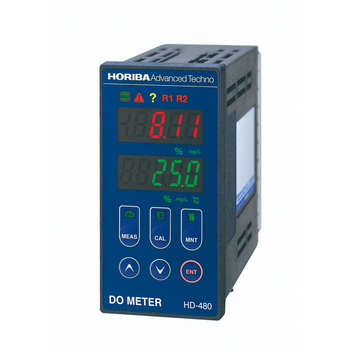
Panel-mount type dissolved oxygen meter (DO meter)

HF (Hydrofluoric Acid) DO (Dissolved Oxygen) Monitor / Pure Water DO (Dissolved Oxygen) Monitor
Dissolved Oxygen Concentration Monitor Series for Semiconductor Manufacturing
Field-installation type electric conductivity meter (conductivity meter)

Field-installation type electric conductivity meter

Field-installation type electric resistivity meter (resistivity meter)

Field-installation type electric resistivity meter (resistivity meter)
Field-installation type water quality measuring instruments
Field-installation type dissolved oxygen meter (DO meter)
Field-installation type dissolved oxygen meter (DO meter)
Panel-mount type dissolved oxygen meter (DO meter)
HF (Hydrofluoric Acid) DO (Dissolved Oxygen) Monitor / Pure Water DO (Dissolved Oxygen) Monitor
Dissolved Oxygen Concentration Monitor Series for Semiconductor Manufacturing
Field-installation type electric conductivity meter (conductivity meter)
Field-installation type electric conductivity meter
Field-installation type electric resistivity meter (resistivity meter)
Field-installation type electric resistivity meter (resistivity meter)
Panel-mount type conductivity meter (conductivity meter)
Carbon Sensor Conductivity Meter (Low concentration type)
Panel-mount type conductivity meter (conductivity meter)
Panel-mount type resistivity meter (resistivity meter)
Resistivity Meter for Semiconductor Cleaning Processes
Citric Acid Monitor
Panel-mount type 2-channel conductivity meter (conductivity meter)
KOH Monitor
Wide range TMAH Concentration Monitor
High Precision TMAH Concentration Monitor
Carbon Sensor Conductivity Meter (High concentration type)
Panel-mount type conductivity meter
Carbon Sensor Conductivity Meter
Flat Carbon Sensor Conductivity Meter
Carbon Sensor Resistivity Meter
Panel-mount type 2-channel electric resistivity meter (resistivity meter)
2-Channel Resistivity Meter
Low Concentration Monitor- Sulfuric Acid/Hydrogen Peroxide
HF / HCl Concentration Monitor
Low Concentration Type HF/HCl/NH3 Concentration Monitor
Field-installation type ORP meter
Field-installation type ORP meter
Panel-mount type ORP meter
Field-installation type polarographic residual chlorine meter
Field-installation type residual chlorine meter
Panel-mount type galvanic residual chlorine meter
On-line TOC analyzer


")
")
")
")
")
")
")
")
")
")


")
")
")
")
")
")

")
")
")
")
")
")
")


")
")
")
")
")
")
")


")


,HE-960LC")


")

")


